
LNK3296G-TL with different output frequency.
Hello.
Recently I acquired, via Digikey, some LNK3296G-TL to build a 15V~5W power supply. I'm using a typical buck topology and I follow the application note and datasheet to determine my resistors/capacitors values.
The converter is regulating the output at 15VDC as designed. However, the operating frequency is between 22kHz and 16kHz. I know that the variation is because of Jitter but I don't understand the low frequency. It was supposed to be around 66 kHz. I tried to vary the feedback and external resistors but without success.
My input source is set to 100 VDC and the inductor has 1.2mH and I am using a 68-ohm resistor at the output leading to a 3W consumption.
Could you help me solve this problem?
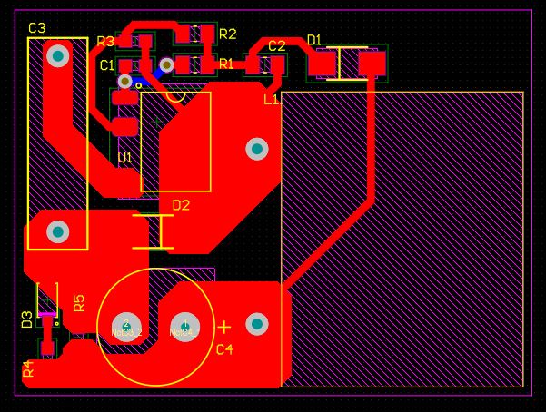
I send the schematic, the pcb, and the waveforms attached. In blue the inductor's current, in green the Voltage Drain to Source (VDS), and in red the output voltage.
Files
| Attachment | Size |
|---|---|
| schematic.JPG | 43.93 KB |
| pcb.JPG | 91.22 KB |
| 20201127_120202.jpg | 2.42 MB |
| 20201127_120043.jpg | 2.47 MB |
| 20201127_120123.jpg | 2.54 MB |
Comments
Hi Jango,
Thanks for the help.
My biggest problem was the audible noise that I thought was the inductor frequency oscillation coming from the ON / OFF control.
I tested it with a higher inductance value to take it out of the discontinuous conduction mode (approx. 2mH) but the average frequency decreased, keeping it in the same conduction mode.
Finally, I reduced the inductor to 500uH, and I got variations with higher frequency and the audible noise stopped. I believe that the inductor was close to saturation in my fast design.
Hi victorfg,
Thank you for providing the design files.
What you are observing is normal behavior for LNK-TN2 family of ICs. LNK-TN2 actually has ON/OFF feedback control, instead of traditional fixed frequency PWM control. The 66kHz in the datasheet is the maximum frequency for this device. You can read more about feedback and ON/OFF control in the device datasheet (Functional Description, page 3).
You can do a quick calculation of output power using the scope measurements and P=0.5*L*I^2*Fsw=0.5*1.2mH*(640mA^2)*16kHz > 3W, so this operating frequency is realistic.
I also noticed that you can still reduce the inductance which can improve your efficiency. For that, I recommend you use the PI Expert online tool which can provide you with optimal component sizing for your design.
https://piexpertonline.power.com/