
LNK306 500~1.000kHz Oscillation failing CISPR Conducted Emission testing
I've got a question with regard to the LNK306.
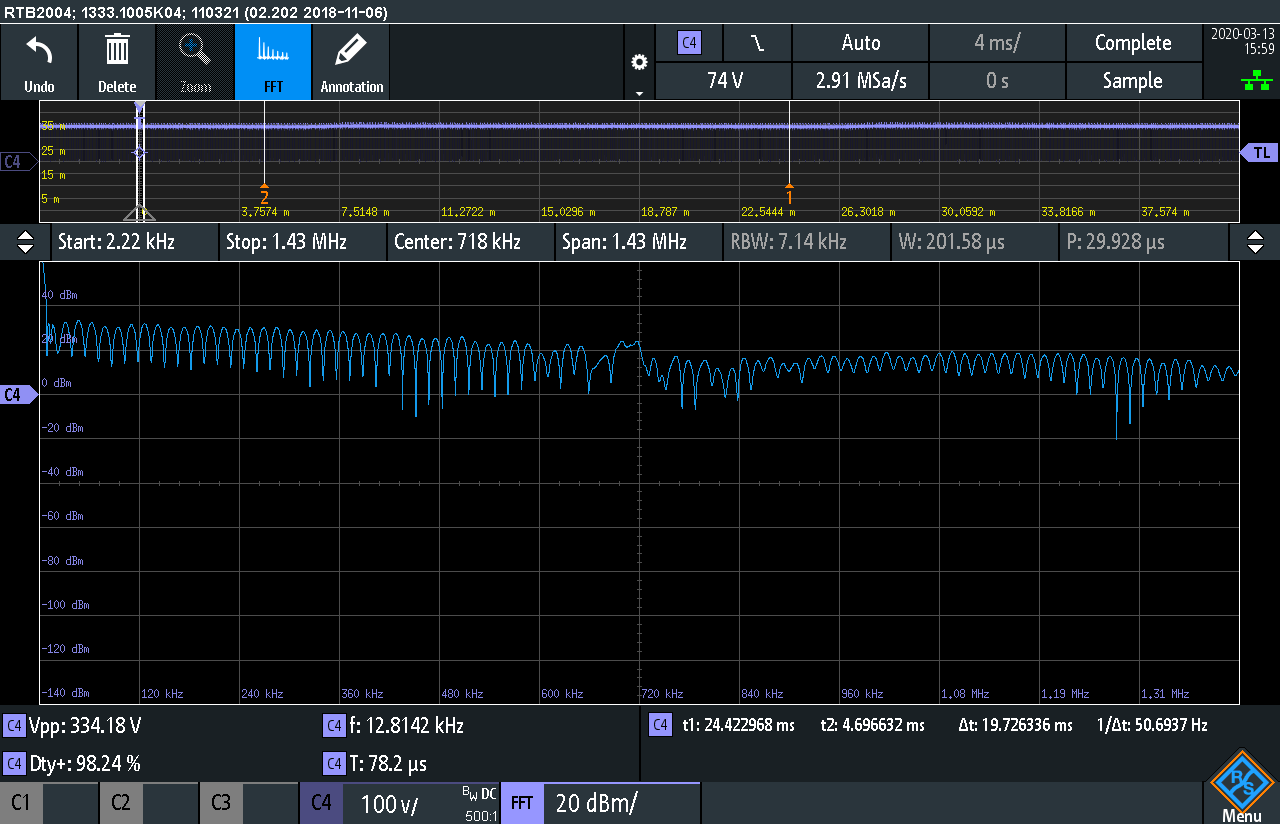
In our application the output of the chip creates an oscillation around 800kHz which goes out of spec during Conducted Emissions testing.
The oscillation frequency does not drift / change over time, it is also not depending on the amount of power drawn from the output. The oscillation frequency is affected by changing components and/or the board layout(but the amplitude not so much).
By using the recommended filtering and board layout we can get the normal switching noise well below the CISPR limits but the 800kHz peak amplitude remains unchanged.
The attached FFT https://ac-dc.power.com/sites/default/files/forum/files/SCR97.PNG image shows the level of noise is around the same level of the normal switching noise but the PI filter on the input does net prevent his from getting fed back to the mains grid.
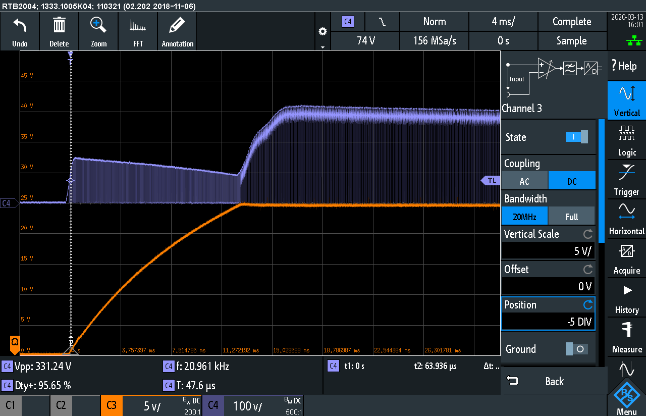
During startup there is no oscillation on the output, there is a very steady/clean switching signal until it reaches the required voltage.
![]() https://ac-dc.power.com/sites/default/files/forum/files/SCR100.PNG
https://ac-dc.power.com/sites/default/files/forum/files/SCR100.PNG
The LISN measurement clearly shows a 966kHz spike above the switching signal.
![]() https://ac-dc.power.com/sites/default/files/forum/files/image.png
https://ac-dc.power.com/sites/default/files/forum/files/image.png
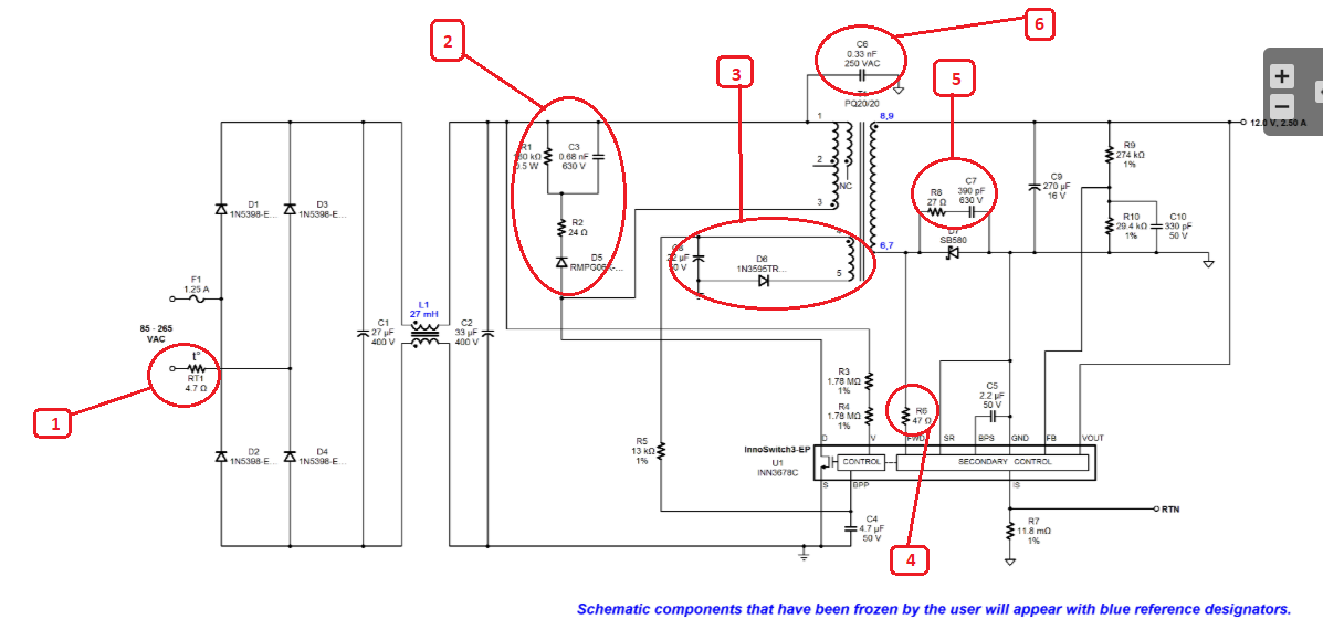
When checking the design with a near field H and E probe the 800kHz signal is the strongest measured at L4 (see attached schematic).
![]() https://ac-dc.power.com/sites/default/files/forum/files/LNK306_schematic.PNG
https://ac-dc.power.com/sites/default/files/forum/files/LNK306_schematic.PNG
We've changed the layout (groundplane) and the inductors (different types) but this only results in the frequency slightly changing to a higher/lower frequency but not an increase or decrease of this signal.
Can you give us any pointers with regard to origin of this oscillation in our implementation/the LNK306 and how to resolve this.
The output voltage of our circuit is 24 volt with an approximate load of 15~50mA depending on the state of the application.
The ripple on the 24V output is well below 200mV and does not contain the 800kHz oscillation.
Files
| Attachment | Size |
|---|---|
| D-S measurement | 51.62 KB |
| D-S measurement 2 | 61.28 KB |
| D-S measurement 3 | 47.61 KB |
| D-S measurement (FFT) | 51.55 KB |
| Startup - signal is clean until output reaches 24V (nominal voltage) | 82.29 KB |
| LISN Measurement | 189.84 KB |
| Schematic | 33.79 KB |
Comments
Is it possible to e-mail them instead of posting them in the public forum?
Hi,
Have you tried increasing the inductance of the Pi filter? A larger inductance may help reduce the EMI spike if it is differential mode noise.
Regards,
Yes we've tried. we tried multiple filters this does not prevent the oscillation of the MOSFET and has only limited effect on the peak amlitude of the oscillation measured in the conducted emissions test. We have another design incorporating the LNK306 which does not have this oscillation. We've been trying to fiend the key difference between the designs and have not found anything critical yet. What we did find is that when we connect a differential probe (50Mohm / 1,25pF) between the Drain and Source of the MOSFET this design also starts to oscillate. After doing some more tests we found that adding a loos wire with a lengt of about 10 centimeters to the source pin of the MOSFET it also causes the otherwise normally functioning design to start oscilllating. The IC/design seems verry susceptible to oscillation based on electric/inductive coupling. Is there an easy way to make the LNK306 MOSFET less senstive ?
P.s. if you wan't me to share the board layout please provide me with a non public way of sharing it (e-mail).
Hi,
Could you send me your email address here and I'll reply privately? Thanks.
Regards,
Hi,
Could you also send me the layout as well? Thanks.
Regards,